The VW Carburetor System

by Robert Kuhn


The VW Carburetor System

Between 1961 and 1974, VW used a variety of carburetors. They all work on the same general principle.

The fuel system consists of a front mounted fuel tank connected through a line to the fuel pump. An eccentric cam on the distributor drive shaft operates the mechanical fuel pump which delivers fuel to a downdraft type carburetor (ie: Solex).

All carburetted VW's use an oil bath type air cleaner (unless yours has been replaced with an aftermarket paper/foam element type).

There has been six different Sloex downdraft carburetors used between 1961 and 1974. Below is a brief description of each:


28 PICT
1961 - 1963

This was the first VW carburetor equipped with an automatic choke. A vacuum piston opens the choke butterfly slightly when the engine starts. This model has a power fuel system which means that it draws fuel directly from the float chamber under full load and high speed conditions.


28 PICT-1
1964 and 1965

This model is very much the same as the 28 PICT except that a vacuum diaphragm replaces the vacuum piston. This model also did not have a power fuel system.


30 PICT-1
1966 and 1967

This model is similar to the 28 PICT-1 except that it has a larger venturi. This model also does not have a power fuel system.


30 PICT-2
1968 and 1969

This model is like the 30 PICT-1 except that it does have a power fuel system.


30 PICT-3
1970

This model is similar to the 30 PICT-2 except that redesigned idling permits the throttle to completely close at idel, while idle speed is controlled by air bypass around the throttle.


34 PICT-3 and 34 PICT-4
1971 - 1974

These two carburetors are similar to the 30 PICT-3 except a bypass mixture cuttoff valve replaces the pilot jet cutoff valve, and the venturi is larger. Although all 1971 thru 1974 carburetors are 34 PICT types, differing choke parts prevents interchangeability. On the 1972 models, preheating was improved and so a new element was used. These are identified with 60 on the choke cover.


Removal and Installation.
  1. Remove the air cleaner.
  2. Pull the fuel line off. Place a rag under the fuel inlet of the carburetor, this will help catch any fuel that might drip out. You might have to clamp the fuel line.
  3. Remove the vacuum line.
  4. Disconnect the electrical connections (be sure to label them) -
    • 1961 - 1970: Disconnect the automatic choke and pilot jet cutoff valve.
    • 1971 - 1974: Disconnect the automatuc choke and the bypass mixture cutoff valve.
  5. Disconnect the accelerator cable from the throttle linkage.
  6. Remove both carburetor mounting nuts.
The carburetor can now be removed/lifted from the intake manifold. Installation is in the reverse order, be sure to use a new gasket that goes between the carburetor and the intake manifold.

Disassembly.

  1. Remove the five (slotted) screws securing the upper part of the carburetor to the body and lift the top off.
  2. Pull out the float retainer and the float.
  3. Unscrew the float needle valve from the upper part of the carburetor.
  4. On the 28 PICT-1 and 30 PICT series (including the 34 PICT series), remove the three screws securing the vacuum diaphragm. Remove the spring and diaphragm.
  5. Remove the three screws that hold the automatic choke.

    Remove the ...

    • Retainer.
    • Spacers.
    • Choke.
    • Plastic cap.
  6. Unscrew/remove the air correction jet.
  7. On the ...
    • Solex 28 PICT, 28 PICT-1, 30 PICT-1, 30 PICT-2 and 30 PICT-3, unscrew the pilot cutoff valve.
    • Solex 34 PICT-3 and 34 PICT-4, unscrewthe bypass mixture cutoff valve.
  8. Now remove the the main jet plug, seal and main jet.
  9. On the ...
    • Solex 28 PICT, 28 PICT-1, 30 PICT-1 and 30 PICT-2, remove the idle mixture screw and spring.
    • Solex 30 PICT-3, 34 PICT-3 and 34 PICT-4, remove the air bypass screw. CAUTION - Do not remove the volume control screw near the air bypass screws. These are factory preset and must not be removed or adjusted.
  10. Remove the cotter pin.
  11. Now remove the four screws that hold the accelerator pump cover. Remove the cover, diaphragm and spring.
Viola! That's it! You've just disassembled your Solex. Pretty simple, eh?

Cleaning.

Just about all auto part stores have some sort of carburetor cleaning solvent. Some come in the form of a spray can while others, the kind I use and recommend, come in a can (about the size of a paint can) which has a little basket inside the can in which to submerge your parts. A company called Gunk makes something called "Carburetor Dip", or at least they used to (it might be called something else now) which is what I use. It comes in a paint can with a small basket in which I can submerge my parts.

Use compressed air to dry the parts. If you don't have access to an air compressor, most auto part stores and electronic part stores (ie: Radio Shack) sell compressed air in a can which also works fine. Aside from the automatic choke, clean all the parts. Use a clean cloth to wipe the choke. To clean the jets (and all the drillings in the carb body), I recommend using compressed air rather than a piece of wire or pins. You can run the risk of enlarging the holes.

Reassembly.

It's in the reverse order in which you took it apart.

I recommend using a rebuild kit when it comes to reassembling your Solex. They don't cost all that much, about $10.00 (US) the last time I checked, and they include everything but the float and jets. It's a good investment.

Solex PICT-2

Other Solex's are similar
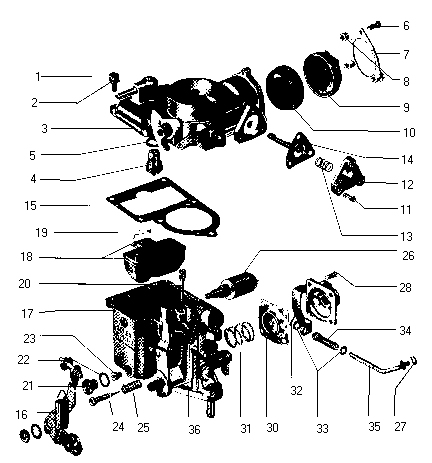
1 Carburetor upper half screw 13 Diaphragm spring 25 Spring
2 Spring washer 14 Diaphragm 26 Pilot jet cutoff valve
3 Carburetor upper half 15 Gasket 27 Circlip
4 Float needle valve 16 Accelerator cable return spring 28 Fillister head screw
5 Needle valve washer 17 Carburetor lower half 29 Pump cover
6 Retaining ring screw 18 float and pin 30 Pump diaphragm
7 Retaining ring 19 Float pin bracket 31 Diaphragm spring
8 Retaining ring spacer 20 Air correction jet 32 Cotter pin
9 Automatic choke 21 Main jet plug 33 Washer
10 Plastic cap 22 Plug seal 34 Connecting rod spring
11 Fillister head screw 23 Main jet 35 Connecting rod
12 Diaphragm cover 24 Volume control screw 36 Accelerator pump injector tube


Back to Library Back to Fuel