I originally submitted the following collection of posts covering aspects of my first full engine rebuild experience to the type2 mailing list during the summer of '97. They record the kinds of obstacles a novice rebuilder faces, as well as my personal observations and questions along the way. These, as well as the cost breakdown/parts checklist should provide sufficient information for you to decide whether to attempt your own engine rebuild, buy a new engine, or just run in horror from air cooled VW ownership before it's too late!
Keeping a journal of your rebuild experience will help you the next time and you'll have a great record of what went into your engine. Now, a year later, rereading my own account helps me retain what I've learned. During the rebuild, just around the end of every month (it took three months total) I kept expecting that I'd have the engine finished and I'd be driving the bus to the next VW show. The shows came and went. Parts were ordered and sent back for quality reasons. Money grew short and I waited for the next paycheck to order "the last part". Nothing's ever as simple as it seems...
Happy rebuilding!
I pulled the engine on my '71 for the final time yesterday. I'm contributing the following data on its condition and comments/speculation on its lifespan. Total miles on the bottom end: 71k; 57k on the heads. When I originally installed it in '92, I wondered what the circumstances would be surrounding its eventual replacement (would I know when its useful life had passed before it died?--would it unexpectedly catastrophically fail or not give a reasonable life?). I had no aircooled VW experience to go by then, though I knew these aircooled engines would never match the life before a needed teardown of the Ford V8s to which I was accustomed. Five years and 71,000 miles later, I'm satisfied with the service it's given and I've learned a few things that will help me as I build my next engine. The engine I'm commenting on is a 1600 single port with stock 85.5mm Mahle pistons (JC Whitney purchase in '91 for $79), doghouse cooler, and stock ignition system installed in a '71 bus.
The shortblock (rebuilt by Mofoco, bored .020 over) cost me $259 back in 1991. When I assembled the engine, I did not calculate CR--this was my first VW engine experience and I basically slapped things together using the Muir book. My single port heads, rebuilt by a friend in '93, have clocked 57,000 miles. The engine was still running and "propelling" the bus as a daily driver when I removed it yesterday--last compression check in May '96 I recorded 135-145 on all cylinders, which is about what it has been during its entire life, #3 always a little lower than the rest. Needless to say, I've been careful to retard timing somewhat, run a little rich, and use premium gas throughout the its life. For the next engine I'm building from the bottom up, and I'm planning on having a CR of 6.8 or 6.9:1 and using regular gas.
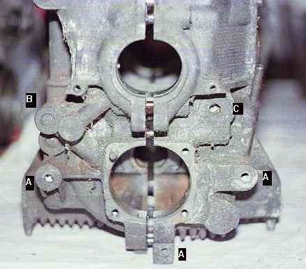
(Pictured below is a bus case. The three "A"s indicate where the rear engine carrier attaches, the "B" is the area that gets spot faced, drilled and tapped for the full flow oil fitting, and "C" is an allen head plug that when removed, is a convenient location to install an oil temperature sender. I use a dipstick sender to measure temperature on my engine.)
Aside from the heads approaching the the magic "60k mile valve drop number", the bottom end has spent its waning months vibrating me and the bus to the ends of our wits. As a result of this, many tin screws fell off and I discovered yesterday that the bolt holding the thermostat to its housing had dropped off. I'm sure my shifter linkage bushings have worn as a result of this vibration transmission, causing the shifter to rattle as it now does. I also noticed yesterday that the right side front tin piece that covers the #1 pushrod tubes was held by one remaining screw and apparently has been vibrating against the case, cutting a deep, long gash into its magnesium flesh by the lower engine-transmission stud (!!). A few thousand more miles of this and I'm sure the case would've been bleeding oil from this wound. (As a side note, I installed new motor mounts five years ago. The transmission rubber mount is original and uncracked. I recently learned that the transmission mounts for the early baywindow bus are NLA.
Since I only installed temp and pressure gauges last year, I only have figures covering the last 10k or so miles. I know that when the oil measured at the dipstick reached 180F using 10w40, the oil pressure would be about 10psi at idle and any warmer, would dip to 6-9 psi at idle, triggering the dash light. On long highway runs I'd see temps as high as 260F. The next engine, balanced and full flowed, and with strict attention to tinware details, I expect to run considerably cooler.
Another symptom of age I noticed about 10k miles ago was that my crank endplay was out to .020" and could not be corrected. When I added the correct shims, the crank would sieze when I attempted to rotate it. I attributed this to the thrust bearing having pounded out the case and have driven it this last 10k miles knowing the engine's death was imminent. I noticed another sign of wear shortly after that when there were nonmagnetic metal particles in my oil strainer. Probably piston or bearing material--but most likely bearings. Needless to say, I won't be reusing this doghouse cooler on my rebuild.
The loud, low frequency reverberation I heard and vibrations I felt were telling me the main bearings were worn and I expect the high CR and unbalanced engine contributed to shortening their lifespan. These vibrations were also probably responsible for stress cracking the cheap muffler I installed only 6k miles ago (despite its simultaneous propensity to rust out quickly) and causing the air flap in one of the heat exchangers to rattle off its hinge and the heat exchanger shells to crack in places.
Basically this engine was not ashamed to tell me it was dying! I'm hoping that among other things, a good balance job, full flow, and low CR on my next engine will help my bottom end last 100k miles before it starts groaning again and telling me it needs serious attention. In the future I'll use silicone sealer on the tin screws to hold them in and dampen any normal vibration. The gash in my case from the macheteing tin (I won't be using that case for my next engine) is making me wonder if it would be wise to affix a rubber seal on the edges of the tin--both to help with sealing air and to prevent any possible future engine case damage. I'll take any comments on the wisdom of that idea.
I'll know alot more about this engine when I disassemble the shortblock and autopsy its innards. I can say that the head studs were not loose, though I did not check exact torque with a torque wrench yet, just got a feel for them with a box wrench. I already Hooverized the jugs I'll be using on my next engine--my old ones were rusty but all fins were present. The heads were remarkably clean and oil/grease free for their 57k mile age.
Oil cooler nuts came off a little too easy--some oil seepage was present in this area. I'll put checking the nuts or even replacing the seals as a routine maintenance whenever I pull an engine in the future.
I noticed the Brazilian Sachs pressure plate with 37k miles on it has unevenly worn fingers--some have a sharp ridge and others are worn flat. I'm wondering/guessing if this wear is attibutable to the considerable crank endplay since the clutch engagement was somewhat harsh going into first. I'm also replacing the clutch flexible tube since it's brittle and revealing it's metal core.
Hopefully I've learned enough lessons from this engine to make my next bottom end last 25% longer or more. However, I'm spending considerably more than 25% than what I paid in parts to build my engine five years ago, so I can't say that my planning will result in an overall cost effectiveness. In fact, for the money I'm spending on my current rebuild, I could probably assemble two "less conscientiously built" engines and perhaps squeek a little more life out of the two combined compared to one really good one. But with all I know now, I can't say I'd trust a lesser built engine to take me across country (so too much knowlege can be an expensive curse, but it also might save your ass when it really needs saving!). Seven or eight years/100k miles from now I'm sure I'll have some more opinions on that.
I also pulled the transmission yesterday since I'll be replacing the shift linkage bushings. I noticed the front left top portion in the nosecone area has some wear from abrasion. I'll investigate the cause of this, but I'm speculating my worn rear shocks that were probably also responsible for my wheel bearing housing wear might also be the culprit here. I'll check for the source of the abrasion and report back to the list if it's interesting.
Hopefully I'll finish the gobs of remaining work I need to do to get my bus back to a healthy state and on the road again. While I'm enjoying delving into the necessary repairs, I'm also looking forward to the enjoyment of driving a mechanically sound bus again. With a whole lot of luck, I'll have it ready to drive to the Litchfield, CT show on June 22. Fingers crossed.
I'm just about to submit my engine parts (1600) to the balancer and I have a question regarding the brass distributor drive gear. My gear is in good condition in that it hasn't been dropped and the grooves are undamaged, but it has shiny spots from where it makes contact with the teeth on the drive pinion (as I would expect when brass meets steel). I wish now I had measured for play before I disassembled this engine last year, but the milk has been spilt, and now I'll have to do a trial assembly to check for play.
What I'm curious about is if "better builders" replace this gear as a matter of course during a rebuild. Seems this would easily be a source for timing trouble if the wear turns significant in the middle of the part's reuse in a new engine. I notice RMMW sells this gear (111 105 223) for $12.95--cheap insurance, if it's OEM quality. Can anyone comment on the quality of these new (presumeably Brazilian VW gears) and the concern of gear replacement? By the same token, is it a good idea (notice, not "necessary") to replace the drive pinion (113 105 231B) at the same time if a new gear is used? I have a vague recollection that some listmember bought a new drive pinion and was disatisfied with the quality--would like to hear more.
A couple weeks back I posted that I was considering buying a new brass distributor drive gear to replace my basically undamaged, but somewhat age worn old one. I chose to do this because I'm having my engine balanced and I'd like to start with as many fresh parts as possible. I received a response to my original post that wisely suggested it might be a good idea to buy the gear from Berg since part quality from other vendors might be an issue. I bought a lot from Berg for this engine for this very reason, but since Berg provides a Brasilian gear as do the other vendors, I figured I could just buy from a local vendor--all Brasilian gears should be the same anyway, right? Ahem...
My local vendor ordered the part and it arrived last week, packed only in a small sealed plastic bag. The gear was nicked and scratched and unacceptible (most likely damaged before his distributor even shipped it to him). My vendor was also shocked by its condition and very surprised the gear wasn't packaged in a box. The gear was made by a company called "Panglia" or something to that effect (the name on the package was partially obliterated). I can't say for sure that it was Brasilian, could've been Mexican I suppose--there was only a couple spanish words on the package but nothing indicating country of origin. Aside from the damage from careless packaging (I wonder if the same manufacturer would ship bearings in a bag??) I noticed that this gear also was slightly different from the original gear. The edge of the gear ID was chamfered on either end (one side much more than the other) so that the surface area (ID) of the gear where it contacts the crank was greatly diminished compared to the original gear. Also, aside from these problems, the brass was grainy and did not have a smooth, polished look.
My vendor ordered from another distributor and a new gear arrived yesterday. This one was also packaged in a sealed plastic bag (!!), but was not nicked or otherwise damaged. There was no chamfer on the ID, just like the original. I also noticed that this gear was a more orange brass color whereas the defective one was more goldish. The good gear was made in Mexico and distributed by J&L International Marketing.
Having to wade through crap before getting the correct part is no fun. Check those parts from whatever vendor you order from--the engine you save may be your own! Maybe I'll keep a metallurgist on retainer to verify the alloy composition of the various parts I buy. Can't be too paranoid.
Another evening spent in the basement with my inanimate friend, 1600 (he lets close friends like me call him 1584). Most of my time was spent trial fitting the type III air deflector tin (Kool tin) to my old engine following tips in Bob Hoover's article. A year or more ago I casually started the rebuild of my spare engine by derusting and repainting all the engine tin. Last night I took that same neatly painted tin and went at it with a ball peen hammer, smashing down raised portions that conflicted with the Kool tin. Anyone knowing how much care I originally put into prepping and painting my good set of German tin a year ago would think I went mad. But with every hammer blow I just kept thinking "improvement, progress, functionality..." If any purists had trouble going to sleep last night, it was probably my engine tin calling out to you with its wails of pain.
It wasn't really that dramatic. Thoughtful blows in the right places give the clearance needed on the front and rear tin pieces that mount around the lower part of the cylinders. The Kool tin I'm using is stamped VW and I believe Brazilian (purchased from Kyle Wade at Volks-motorsports). It's thicker and stiffer than the aftermarket (Bug Pack!!!) Kool tin I returned to a local supplier a few months ago. It snaps into place on the cylinder studs firmly, but I can see how engine vibration would shake it off PDQ. I drilled some very small holes in the metal wedge of tin that fits between the cylinders and as Bob suggests I secured safety wire from these holes in the center of the tin upward to a bridge formed by two stiff stainless steel rods. The rods are spaced and rest atop the cylinders between the fins, acting as a bridge across the cylinders. The wire from the holes drilled in the Kool tin secures to this bridge, snugging the center of the tin tightly against the cylinders. As an added measure of paranoia, I also drilled a tiny hole on either side of the clips that snap to the cylinder studs and tied wire around the cylinder stud for added security. I think this was overkill though--with the center secured properly the rest shouldn't come loose.
I bought a 1/4 lb spool (around 90 feet) of .032" stainless steel wire. In my search for SS wire I discovered that all the hardware stores I visited and called have galvanized steel wire and brass wire, but that's about it. I went to a marine dealer to get the stainless stuff. It was $12 for the spool (at the boating places they call it "seizing wire"). It's one of those things that you want to build a project around just to use it (anything with a military spec # must be good...).
There's only so much you can do with a hammer and pliers to move the tin closer together to seal the air gaps. Some spots I'll have to go back over with a torch and scrap metal strips to get a tight seal. I began to consider again the problem of the sharp edges of cylinder tin that butt against the crank case. Both my old case and the one I'm using for my new engine were scarred by sharp edges of tin vibrating against it. An ideal solution would be a small, thin lip of silicone rubber that would clip to the edges of the tin that contact the case. Another possibility is to use blue Permatex to cushion the edges near the case--that should hold up to the heat so I might try that. I still have to get some extra foam to wrap around my new oil cooler so I'll look into the silicone edging possibilities when I shop for that.
I noticed last night when I removed the single port heads off my old engine (50k on rebuilt heads) that all the combustion chambers had a crack bridging the intake and exhaust valve seats. (Similar cracks around seats and spark plug hole are pictured below on this dual port head.)

Checking the cylinder bores I also noticed that just below the TDC ridge for about a half inch there is a smooth ripple pattern as if the piston in it's journey down or up just below TDC shimmied a bit. All the cross hatch on the piston travel area of the bore was gone (71k miles on P+Cs). I still had good compression on this engine (120-135) when I decommissioned it but I was getting a bad vibration and it didn't have that nice, even, balanced tone to it. Probably the main and thrust bearing wear that caused the crank to slop around also show their affects here on the tops of the cylinders (and I bet the piston skirts were slapping on the bottom of the cylinders which would account for the aluminum flakes in the last few oil changes). When I've completed the tin fitting I'll split the case and find out some more. I'm eager to examine the rod bearings since I know in its waning days this engine was really loose and sloppy.
I placed my order for the Berg barrel shims yesterday. Tim at Berg did say that their shims will be no more off than .001-.002". You give them the OD of your cylinder and the thickness you want and they make them up. Apparently they are also wider than the typical shims and have indentations on the OD to align with the head studs. Oh yeah, and the price has gone up from $44 in their last flyer to $52!!--he said due to the cost of labor. I just keep telling myself I'm not really paying that much for a set of shims (it's all a bad dream). BTW, a listmember offered to take my Bug Pack shims down to the smallest shim on his surface grinder to make them a useable set. I removed the rough edges from the stamping on all of them and three measured between .053-.056" while one was standing tall at .065". Using a .053" set would raise my CR by a little over a tenth. Not bad, but since I'm maniacly obsessed beyond reason on this issue now I'm getting the proper .060 shims and getting my 7.0:1 if it kills me (or drives me to the poorhouse). The new shims should arrive by the end of next week (looks like I won't make the Terryville show afterall).
Having recently sealed my case I can comment on some of the mistakes I made and a few potential problems to avoid. These of course do not include the errors I made that I did not detect ;):
1) Chase the threads on all your case studs before you attempt to assemble anything. I assembled and sealed my case and then when I attempted to install the oil pump I realized I had to back out the studs a bit to get the nuts on completely. That's when I damaged some case threads, which apparently had frozen to a stud. At that point I chose to tear everything down and tap the case for a 10/8mm stepped stud (though you could carefully catch the metal filings from tapping in this area without a teardown, I had additional incentive for disassembly--see tip on cam lube below). Check that the nuts will go down far enough on the stud by fitting the pump and cover on both halves with the case split open (i.e. before you seal your fate with Permatex 3H!).I'm still waiting for some last pieces (barrel shims) to arrive in the mail so that I can complete my engine. My shortblock is done, I have yet to make the final assembly of the longblock, turn the key, and feel either the thrill of victory or the...well, that thing I'd rather not talk about. I figure I won't feel completely thrilled until I've logged my first 50k trouble free miles anyway.2) Read through all your manuals a few times again just before you dig into the job and keep notes on critical points. Some information I knew, but I forgot to apply it when the time came. Though some of these points were minor, I felt compelled to disassemble and start over (knowledge of little things left undone can be haunting).
3) Grease/assembly lube should not be used on the lifter bores (or cam lobes)--use STP. This is advice from Berg and others "in the know". Berg offered a personal "statistic" that on 97% of the camshafts he'd encountered during engine disassembly that had flat-worn cam lobes, grease/moly was originally used as an assembly lubricant. STP mixes nicely with the oil, protects and sticks to the parts for the time you need it and won't plug up small oil passages as grease might.
4) In the Wilson book, after he describes how to position the crank relative to the cam he immediately proceeds into installing the drive gear and distributor and tells you to position the distributor rotor to the #1 firing position. What's left vague here (at least to me) is he doesn't mention you have to rotate the crank 90° in order to do this. His description left me falsely thinking that when the cam/crank dots are properly lined up, you can then just install the distributor drive gear/distributor and it will be set to fire at #1. This is not true of course--when you rotate the crank 90° more you'll then see the #1 rod is at its full stroke, bringing the imaginary piston to its TDC). Thanks to Will Wood for clarifying this for me.
5) Bob Hoover makes a great point I don't see mentioned in any of the texts. He suggests pumping oil through your passages with a garden sprayer prior to cranking it over so that you never have to run the engine "dry". Other books only mention removing the plugs and cranking the engine over till the oil light goes out. Bob's way--insuring that there is oil in the passages to begin with--makes a lot more sense. To accomplish this I bought an M10x1.00 thread brake bleeder valve at Pep Boys and opened up the end a bit to allow quicker flow. This gets threaded in the OP switch hole and I'll then use a hand pump with a line going to this fitting to get oil in the passages before I attempt to crank it over. If you're running a full flow filter, remember to fill it with oil before installation. (Note: The oil pressure sender hole threads are tapered. It's best to use a tapered fitting so threads won't be damaged. I did not thread the bleeder fitting far, just until resistance was met, which avoided marring the threads, but provided the oil tight fit required).
6) Lap your valves--even if you have new heads. Valve sealing is important and shouldn't be assumed.
7) After you're clever enough to check that the valves seal, don't space out and install your valve springs upside down. Like, who would do that? :-|
8-infinity) It would be futile to attempt to list all the difficulties you could encounter (it's obviously a lot easier to write a manual saying what to do rather than warning you all the ways you could do something wrong). And everyone has a unique, personal and sometimes complex process of erring. How's that for depressing ;)!
(Below: Here's an example of a detail that left unnoticed might haunt you later. On the left is the 30 amp generator tin commonly found on beetles. To the right is a 38 amp bus generator mounted to its similar, but special tin piece. Notice the bug tin is convex, while the bus tin is concave to accomodate the longer 38 amp generator. If you replace your generator during a rebuild (they will be stamped 30 or 38 amp) be certain you have the correct tin for it, or misaligned crank and generator pulleys will result in losing fan belts regularly.)

Last night the pistons and heads went on and I torqued down the whole happy package. It took hours of cleaning, oiling, sealing, double checking, torquing, and re-torquing for this seemingly simple accomplishment. Looking back on the evening I really don't know where the precious minutes went. I spend a little too much time admiring my work or thinking (unecessarily!) when I'm working on the engine. I'll have to set up a video cam next time so I can playback and figure out where the time goes.
A few things worth mentioning but nothing earth shattering since the task of installing the pistons and heads is simple and well explained in the books. A note to myself: I have to watch myself when using the crinkle band ring compressor. The last time I used the thing was about 7 years ago when I installed my last set of pistons. This time I tightened the adjustment screw a little too tight and scratched a small area of the piston skirt with the sharp edges of the "crinkle band". I'll have to control myself better next time or just use a simple c-band type compressor.
The Kool tin went on nicely and fits very snugly and securely. I had rehearsed my plan to secure them on my old longblock a couple weeks ago. I drilled a tiny hole on either side of each of the clip points on the KT that grab the studs. I threaded the stainless wire through these and around the stud and then twisted the wire down snugly for each stud (except the two inner center ones which are somewhat hard to reach this way. The problem with this grand scheme is that it's time consuming to fiddle with each little bit of wire, place it and tighten it down just right--while all this is happening the silicone under the jugs wants to set (can you blame the poor stuff?!) so securing the tin this way is like playing beat the clock (probably the reason, I kept ruefully thinking, that Bob recommends another way!). Unfortunately I think I didn't beat the clock as well on the 3/4 side so I won't be too surpised if I get a bit of oil seepage around the jugs from torquing down on semi-cured silicone. If I had to do it again I might go with Wilson's recommendation of using the 3H for the barrels since that seems to allow more time before cure (the high temp silicone RTV cures fast, especially a thin coat). I like the idea of each clip point being secured by wire, but I'll tentatively conclude this idea might work best in a theory ;).
I had the engine mounted on its stand and kept rotating it and torquing the heads down bit by bit, side to side, criss-cross, inner to outer----man, I was all over it! This is when I really feel I get my money's worth from my inch pound beam-style torque wrench. It's nice to watch the beam gently creep to its desired point evenly for each stud. I'm going to treat it to a special clean and polish when I'm done (don't tell its big clicker-type brother--we don't want jealousy in the toolbox).
The not so amusing part of the evening was when I kept dropping the same wrist pin circlip in the engine three times in a row. You'd think after the second time I'd think to cover the spigot bores before getting near them with the clip. I guess I just like the challenge of shaking a tiny, light circlip out of an engine case (or maybe I'm repressing a desire to split the case one last time to check that everything's ok--ummm, no I think it might be just garden variety stupidity at work here ;). I used the more traditional circlips that Berg provides with their piston sets, not the standard VW wire type. I used them because I had them--I've never experienced problems with the wire type.
So the longblock is together. Tonight I'll fasten on the external doodads and the day after new engine will meet old bus. That light at the end of the tunnel is getting brighter!
(Pictured below is an air dam that clips to the fins on the underside of the head. A new one is not included when you buy a new Brazilian head. If the deflectors on your current head are rusty like this one or missing, make a replacment. They serve to direct the downward cooling airflow across the fins. If you make your own, for the right side head air dam you need to cut a notch to accomodate the thermostat rod.)

Below is the sealing frame, VW part # 113 117 323, (sometimes affectionately referred to by Type2 list members as the "Hoover bit"), a piece of often discarded tin that mounts to the oil cooler, sealing an otherwise open area. Its omission allows precious air to escape, reducing flow over the cooler. Sadly, this important part has been obsoleted by VW, so if yours is missing or terminally rusty, you should fabricate one or locate a good used one.

I've given head torque/retorque and stud treatment some research and thought lately (a little too lately) and have a few comments. In my "research" I notice Bentley and Wilson do not specify using anything on the outer head stud threads or under the washers (Wilson does of course recommend Permatex 3H on the stud to case threads). Usually when a manual does not mention anything, I think a light coat of oil on the threads is assumed (Muir does mention using oil on the stud threads). Both Hoover and Berg recommend using high temp silicone under the head washers and Bob as I recall also uses Loctite on the threads. This makes a lot more sense--you don't want to give the washers or nuts the opportunity to move around with all those heat cycles coaxing them to do otherwise. I'd wager Loctite is a better choice than anti-sieze since it not only inhibits corrosion but it makes the nut stay put.
Despite this wisdom of the ages, very unfortunately, when I installed my heads recently I had the Wilson book on the bench at the time to use as my reference and I forgot the sage advice of using sealers on the threads/nuts. I just put some oil on the threads and torqued the heads down. I'm doing my first head retorque in 300 miles and I have considered correcting this problem by removing the nuts/washers at that time and adding the silicone under the washers and loctite on the threads. But after some thought I've concluded it wouldn't be wise to remove the nuts--seems adding torque at this point makes sense, but removing the nuts to clean the threads or retroactively apply sealer allows the stud to relax and that would defeat the purpose of a "retorque" as I see it. I've tentatively resolved to forget adding the sealers and just check the torque and add additional inch pounds if necessary to bring it up to spec and then recheck the head torque (as Bob mentioned in his post) everytime I have the engine out for a repair. And of course, for the next engine I'll use the sealers in the first place. :|
The short version:
My newly rebuilt 1600 starts, runs and best of all, it doesn't leak oil! Wooohooo!
The details:
I spent the entire weekend working to finish this job. The better part of saturday I spent making a very sturdy bracket for my full flow filter mount. I waited to do this after the engine was installed so I wouldn't have to go by measures and guestimations with the engine out--instead I just physically routed the lines and then determined how I'd mount the filter where I wanted it. My simple requirements were that the filter must be vertical, much further from the ground than the engine support bar, and away from the muffler. I was limited by the 20 inch hoses that came with the kit I bought awhile back from Berg and that I am committed (at least financially!) to using for a short while. As Bob says in his sermon, these kit hoses are very short (and they're only 3/8" ID not the desireable 1/2"-this is something I will change before the cold weather hits). If you plan to mount a filter, I'd say the minimum hose length requirement would be around 25" each. That way you won't have to snake short lines between exhaust pipes (I insulated mine with 3/4" heater hose clamped over the braided oil hose to protect the braid from abrasion where it might rub against metal).

(The photo above shows the location and mounting I used for my full flow filter. The filter bracket is mounted to the bottom of the spare battery tray. The only custom piece is a "T" I made from 3/8" thick aluminum plate scrap. You can see part of the "T" that is held to the tray by three bolts (another three are concealed from view by the filter). I mounted the oil filter adapter to the leg of the "T" with two bolts. On the inside of the tray is another flat piece of 3/8" aluminum plate to serve as reinforcement. Before bolting it all down, the area was cleaned and blue silicone was used between the layers of steel and aluminum as a gasket material. Exposed sheet metal was later painted).
Tim at Berg advised against anything longer than 20" hose, though it was so long ago when I ordered this kit I can't recall his point. I did inquire about the adequacy of the 3/8" ID hose citing Bill Fisher's claim for a minimum 1/2" ID to avoid the possibility of oil starvation to the bearings during cold weather. Clyde said that aspects of Fisher's book are dated and that the 3/8" is sufficient even in cold weather as long as you allow for a warmup period during the coldest days (around 0* F). I'm not convinced though that the increase in flow afforded by teflon could provide the same benefit as an increase in ID of 1/8" so I'm getting the 1/2" (falling back on the better safe than sorry philosophy). What I really want is 1/2" ID teflon hose with braided stainless steel cover and female AN8 fittings (25" long taper to taper)--any vendors out there listening?
The only drawback to my chosen filter location (under the spare battery tray) is that it conflicts slightly with the exhaust pipe from my BN4 gas heater. Once I get my gas torch I'll make a custom exhaust pipe to solve that problem.
I added a plastic battery box to protect my battery tray from corrosion. I'm lucky in that when this bus sat for 13 years before I purchased it 6 years ago, the previous owner had removed the battery so my tray is in great shape--and I want to keep it that way! I also replaced all the electrical connections to the starter and engine harness along with a few wires with brittle insulation. Minutes turned to hours, etc. etc. Details are infinite but fortunately vision is only macroscopic ;).
I think my oil capacity is almost four quarts now--about a quart in the Fram filter, 2 1/2 in the sump and around 1/4 or so in the lines and passages. I had a moment of nostalgia when I took my big filter wrench out of retirement--I haven't used it since I sold off my Ford Galaxy 7 years ago. It's nice to be in the market for oil filters again!
So it starts, runs and doesn't leak oil, but I do have to address a small vacuum leak problem that I'm pretty sure is the result of a loose intake boot clamp. The revs fluctate around 50-100rms at idle on my digital meter and the 34Pict doesn't want to adjust--I found a stripped screw on one of my small intake boot clamps (should've realized that before, but for some reason I didn't do the final tightening of the clamps until the engine was in). Oh well. Once I get that nailed down I should be able to properly adjust the carb and get this bus back on the streets where it belongs.
I'm happy, my bus seems happy (I wish I could flip it upside down and take pictures of the rear quarter--it's soooo clean under there!) and my tools are relieved. Time to sort through and clean up the rubble in my work area and plan my next bus project.
I was finally inspired this past weekend to fully examine the 1600 shortblock I pulled out of my '71 about 7 months ago. I stopped running it at 71k miles. At that time, the main bearing wear was causing the bus to vibrate badly, the thrust bearing was shifting in the case making end play correction impossible, and the oil pressure light would stay at idle after a warmup. It was a Mofoco rebuilt shortblock, type III case modified for upright, bored .020 over, and for the $259 I paid for it in '91 it truly served me well.
A visual inspection of the exterior wasn't promising: loose lower tinware on the passenger side cut a severe groove in the case and a fine crack has begun to run across the path of the groove near the #1 exhaust lifter. The tapped flanges that jut from the bottom of the case that serve as attachment points for the lower tin were in disarray: one was bent outward, another two were worn almost clear through from friction of loose tin, the last one held a siezed screw, and they all were victims to some extent of salt corrosion. No cracks to report in the bellhousing area behind #3 or between the cylinder spigots or around the oil pressure sender. As I suspected, with 35 lb ft of torque on the six large case nuts, the crank couldn't spin without tight spots, so if all else inside looked reuseable, at least it would need an align bore. I also knew before splitting the case that a thrust cut would be inevitable from my wacky endplay measurments.
Splitting the case did reveal a mess in the thrust bearing area. The inner surface of the case over which the thrust bearing sits was pounded and the locating pin for the bearing ripped a path across and behind the surrounding magnesium (it looked to be just barely doing its job keeping that bearing from spinning). [Surprisingly, this engine did not pour oil, though it did leave some drops below it that grew larger in its waning years. It was not however an excessive consumer of oil though it did go through a couple oil seals, especially in the last 6,000 miles when the endplay became unsettable.]
The saddle for the thrust bearing was also badly pounded. (easy determination at this point--that, plus the dowel pin damage means for me that the case is trash). The case bearing saddles were pounded deeply (a whole lot more than just catching a fingernail on the magnesium surface where the bearing left the impression of its back). Also the bearing surfaces that made contact with the crank were in general badly scored. Cam bearings didn't look bad though, and the cam lobes had the typical side wear I've seen on other old 1600s I've torn down--nothing severe. (Picture shows another case, not the one described above. The brown lines on the bearing saddles are common impressions made from the back of the bearings. If this line is a high spot, the bearings have pounded against the saddles--one indicator that the case should be align bored).

The lifters were worn flat and revealed pitting on their faces. I suspect they, as well as the cam, are regrinds since that's how the shortblock was advertised at the time of purchase. I can't say anything bad about them though: my valves rarely required adjustment at tuneup time. Though I never measured it, this engine probably ran an 8:1 CR with rebuilt single port heads and the last pair of heads that were closing in on 50k miles did not suffer valve drop, just revealed typical cracks between seats on teardown. The oil pump was a German Schadek and didn't look bad (no grooves in the aluminum housing under the gears, though the steel cover plate was grooved). The pump goes in the trash anyway though, I don't have enough of the experimenter's spirit to see how much more life it has left.
I didn't measure the crank (measuring equipment in bus--too cold outside--shorts on--too little motivation now), but side by side with a standard crank it appears to have been reground at some point. Considering the light grooving on a couple of the journals (that I easily catch my fingernail on if I drag it with a bit of downward pressure) it looks like it's in for another regrind if it wants to spin again. Brass gear and steel gear look good. All but one of the dowel pins slid out too easily and though I didn't see any ovaling of their holes, I at first suspected that would be one more expense that would eliminate this crank from consideration for future use. But, when I did try a new dowel pin it fit snugly in all three holes. Apparently the hardened dowel pins wore while the tough crank kept its shape. Well, that's nice!
Aside from the tragic story of the thrust bearing dowel pin, the other tiny dowel pins in the case saddles looked good, though, as has been my experience with the other cases I've torn down, they came out too easily for comfort with needle nosed pliers. I wonder if these fit very snugly in a new case?
I removed all the usable studs from the tired case and put it in the scrap pile, RIP. I pulled my other greasy, stripped, spare AE case
onto the bench and looked it over. The saddles don't look bad (very slight pounding) and the thrust surface is good (the lips of an old
thrust bearing grab it snugly). I don't see any markings on the cooler flange or around the front oil seal area indicating a previous align
bore, so looks like this will be its first boring (that makes this post the second boring--
************************************************************************************
I've logged 20,000 miles on the new engine over the past year. Aside from the regular commute to
work, my wife and I drove our bus on vacations from Connecticut to Nova Scotia, Maine, New York
New Hampshire, Virginia and points in between. I don't regret paying the extra money to rebuild the
engine myself since I have been rewarded by the experience and the confidence in knowing that no
matter how far we travel, I have the skills to make any necessary repairs to get us home.
Though the performance of the engine has met my expectations, here are some things I will do
differently in the future or have corrected since the initial installation:
Instead of buying the Berg full flow oil kit with 3/8" stainless steel braided lines, I would instead recommend buying
barbed fittings and 1/2" ID Aeroquip hose (I use the blue hose rated for 250 psi) from a hydraulic shop and
purchasing the filter mount separately. BugPack distributors like Larry's Off Road offer
mounts that accept the Ford style filter with different models that have ports on either the left or right,
or above the filter, depending upon how and where you decide to attach it. Berg is still an excellent source
for the full flow pump cover (with or without the pressure relief valve). Since I've added a second oil cooler,
I swapped over to the 1/2" ID hose and now have about 12 feet of it snaked under my bus. The larger ID is better
for flow and clamped fittings are adaptable to roadside hose replacement (if necessary). I use the heavy
duty clamps (they're twice as wide as a standard band clamp) and have added spare clamps, hose and a
brass 1/2" to 1/2" splicer to my onboard spares kit.
Even if you installed a Berg pump cover with pressure relief valve, use the Fram HP1 filter for your
full flow setup, NOT the lower burst pressure rated Fram PH8A. Some people told me the PH8A worked for them
even in colder weather, but I did not find this to be true. The PH8A will balloon on a cold startup, or worse,
it will explode. I buy a few HP1s at a time from Pep Boys. My local Pep Boys no longer stocks the HP1
(only the new "teflon" Fram filter line) but I can still special order it through them for about $7 each.
I would not again use the stock valve stem oil seals. These became brittle and broke off the stem very
quickly and I subsequently found them in my valve covers. After they all came off, I cleaned out my oil
strainer (where the remainder migrated). Since my rebuild I've learned of a good alternative
valve stem seal that has an outer metal reinforcement to keep it in place. Valve stem seals are not
necessary items on new heads, but if you feel personally compelled to use them I would investigate these
better seals and stay away from the stock rubber rings.
Due to improvements like all new components, the Kool Tin and improved tin sealing I expected my
new engine to run considerably cooler than my previous tired, motor that had relatively well sealed tin
and engine compartment rubber in good condition. While the oil pressure improved dramatically (I retired
my old 71,000 mile engine due to main bearing wear), the oil temperature was approximately the same as
before. I added a CHT gauge after the rebuild, so the only temperature reference I have across both
engines is oil temp. Here are sample readings from the "new" engine, which have remained fairly
consistent over the first 20k miles of its life:
(measured with VDO gauges and senders: dipstick sender for oil temperature,
dual pole sender for oil pressure, cylinder head temperature measured at #3 spark plug)
Next, I added a second oil cooler (doghouse type) and oil thermostat.
Result: maximum oil temp ~20° cooler, though cylinder head temperatures remain unchanged:
Though I measured chamber volumes and deck height and shimmed my cylinders to achieve 7:1 CR, I did
not make chamber volumes exactly equal (though they were very close) and I did not fully polish the combustion
chambers. I used new Brazilian heads, and settled for uneven valve stem heights (both exhaust valves on
each head sat a bit higher than the intakes). For future heads, I will address these details. Also,
I did not retorque my heads as I had planned to a few hundred miles after the rebuild.
Do take the extra time to weld two bolt flanges to the muffler to heat exchanger pipe junction. Stock ring
gaskets and clamps eventually leak causing repeated labor. After welding on the flanges, installation
of the muffler is simplified and there are no leaks. This is an important labor saving improvement worth
the effort to make.
Logging 20k miles/year on a camper bus propelled by a little bug engine requires attentive driving and
conscientious maintenance habits (and you really must love it!). I expect to replace the heads every 2.5
years and completely rebuild every 5. Needless to say, I'm ever in the process of collecting new parts
and reconditioning pieces in preparation for my next engine. The saga and the learning continues...
Back to Main
Newly rebuilt stock 1600cc engine in '71 Pop-top Westfalia

Oil: Castrol 10w40
Speed (MPH)
RPM
Ambient Temperature (F)
Oil Temperature (F)
Oil Pressure (PSI)
Cylinder Head Temp (F)
Conditions
Idle
1000
42
179
30
not measured
Raining; after initial warmup driving
65
3800-3900
55-60
225-235
40
not measured
Highway driving 4+ hours
65
3800-3900
70-75
240-250
40
325-350
Highway driving 4+ hours
Idle
850-900
70-75
220
15
250
Shortly after highway driving
Speed (MPH)
RPM
Ambient Temperature (F)
Oil Temperature (F)
Oil Pressure (PSI)
Cylinder Head Temp (F)
Conditions
65
3800-3900
85-90
210-230 Max.
40
325-350
Highway driving 4+ hours
